Model NO.: HGY29 HGY33
Vibrating Amplitude: 2.0mm
Certification: ISO9001: 2000, CE
Condition: New
Color: Customizable
Motor: 15 Kw
Brand: Saintyol Dawin Machinery
Series: 29m 33m
Key Word: 28m 33m Hydraulic Self-Climbing Placing Boom
Control: Proportional Remote / Wire Control
Column: 22.7m
Boom Arms: Detachable
Valve: Proportional
Trademark: Saintyol DAWIN
Transport Package: Standard Exporting Package
Specification: CE ISO
Origin: Qingdao Shandong
HS Code: 84134000
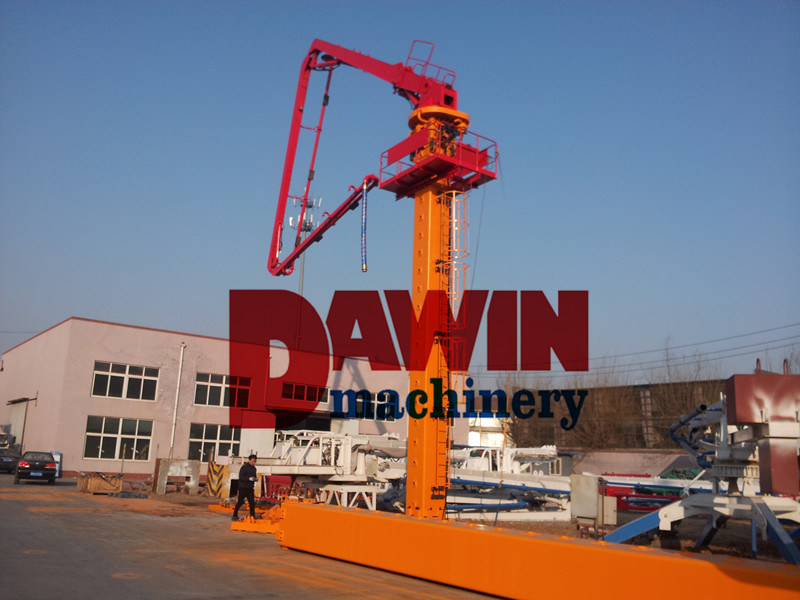
Concrete Distributing Boom with Self Climbing Hydraulic Lifting System
Self-climbing Concrete Distribution Bar in Construction of High-rise Building
Rotary Distributing Arm to Constructing Round Hydraulic Structure Application
Tubular Column Hydraulic Concrete Placing Boom with 29m 33m Placing Arms
29m 33m Tower Concrete Placing Boom with 22.7m Column and Auto Hydraulic
Separate placing booms are used in conjunction with stationary or line pumps in applications where structures are complex, exceptionally high or do not have sufficient space for mobile boom pumps to work. Placed on tubular columns and crane masts, they can climb from floor to floor, enabling quick and efficient concrete placement.
Specialised Concrete Pumping, our specialist placing boom and stationery pump division, has an extensive range of separate placing booms and associated tower and pipeline equipment available to service a range of projects.
Climbing procedures
Self-climbing of the placing booms is conducted along the prepared openings in the floor plates. The steps are as follows:
(1) Climbing of the placing boom is achieved by handling the manually reversal valve. The operator stands beside the floor opening which is especially built for the placing boom to climb up and for the lower climbing frame to be located, so as to control the extension or retraction of the climbing cylinders.
(2) Turn the selector switch on the console to "Self-climbing" position to start the electromotor, and then operate the manually reversal valve to extend the cylinders upward, allowing the half circular holes in the cylinder piston heads to hit the upper-jacking shaft in the tower body. Keep the cylinders extending until the lower-jacking shaft in the lower frame gets loose, and then take it out.
(3) Handle the manually reversal valve upward to extend the cylinders for 500mm, allowing the hole in the lower frame to engage to that in the tower body, and then insert the lower-jacking shaft. In this case, retract the cylinders and the placing boom will fall down with the lower-jacking shaft supporting it. Take out the upper-jacking shaft and insert it into another hole in the tower body.
(4) Handle the manually reversal valve to extend the cylinders, allowing the half-holes in the piston heads to hit the upper-jacking shaft in the tower body. Keep the cylinders extending until the lower-jacking shaft in the lower frame gets loose, and then take it out to start the second climbing stroke. Repeat the above operations, and the placing boom will rise up along the climbing frames.
Cycling times of the cylinders needed for the placing boom to climb up a floor depend on the height of the floor. For instance, a 3m high floor needs 5 cycles.
(5) After finishing climbing, wedge the climbing frames tightly by means of iron wedges. The vertical force of the placing boom is transmitted from the lower-jacking shaft in the tower body to the lower frame, and the horizontal force is carried out by both the upper and lower climbing frames.
Turn the selector switch on the console to "Operating" position before the placing boom shifts to concrete placing.
Finally disconnect the climbing cylinder hoses from the pipeline-fitting plate on the tower platform, and place a part of them on the upper-platform and the other part on the tower platform for future use.
Note: Above parameter is subject to change without prior notice. For the latest technical parameters, please contact us directly.
2.1 Boom
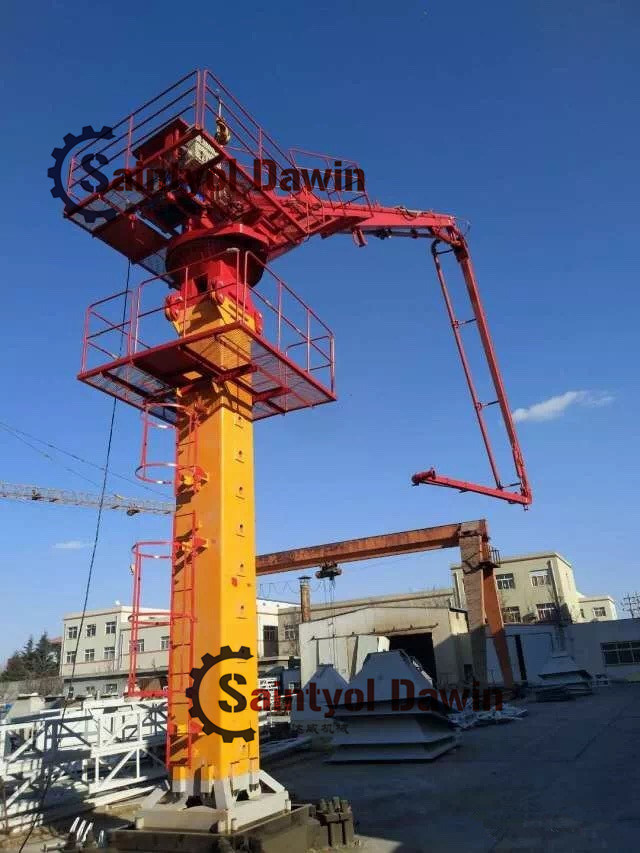
Self-climbing Concrete Distribution Bar in Construction of High-rise Building
Rotary Distributing Arm to Constructing Round Hydraulic Structure Application
Tubular Column Hydraulic Concrete Placing Boom with 29m 33m Placing Arms
29m 33m Tower Concrete Placing Boom with 22.7m Column and Auto Hydraulic
Separate placing booms are used in conjunction with stationary or line pumps in applications where structures are complex, exceptionally high or do not have sufficient space for mobile boom pumps to work. Placed on tubular columns and crane masts, they can climb from floor to floor, enabling quick and efficient concrete placement.
Specialised Concrete Pumping, our specialist placing boom and stationery pump division, has an extensive range of separate placing booms and associated tower and pipeline equipment available to service a range of projects.
Climbing procedures
Self-climbing of the placing booms is conducted along the prepared openings in the floor plates. The steps are as follows:
(1) Climbing of the placing boom is achieved by handling the manually reversal valve. The operator stands beside the floor opening which is especially built for the placing boom to climb up and for the lower climbing frame to be located, so as to control the extension or retraction of the climbing cylinders.
(2) Turn the selector switch on the console to "Self-climbing" position to start the electromotor, and then operate the manually reversal valve to extend the cylinders upward, allowing the half circular holes in the cylinder piston heads to hit the upper-jacking shaft in the tower body. Keep the cylinders extending until the lower-jacking shaft in the lower frame gets loose, and then take it out.
(3) Handle the manually reversal valve upward to extend the cylinders for 500mm, allowing the hole in the lower frame to engage to that in the tower body, and then insert the lower-jacking shaft. In this case, retract the cylinders and the placing boom will fall down with the lower-jacking shaft supporting it. Take out the upper-jacking shaft and insert it into another hole in the tower body.
(4) Handle the manually reversal valve to extend the cylinders, allowing the half-holes in the piston heads to hit the upper-jacking shaft in the tower body. Keep the cylinders extending until the lower-jacking shaft in the lower frame gets loose, and then take it out to start the second climbing stroke. Repeat the above operations, and the placing boom will rise up along the climbing frames.
Cycling times of the cylinders needed for the placing boom to climb up a floor depend on the height of the floor. For instance, a 3m high floor needs 5 cycles.
(5) After finishing climbing, wedge the climbing frames tightly by means of iron wedges. The vertical force of the placing boom is transmitted from the lower-jacking shaft in the tower body to the lower frame, and the horizontal force is carried out by both the upper and lower climbing frames.
Turn the selector switch on the console to "Operating" position before the placing boom shifts to concrete placing.
Finally disconnect the climbing cylinder hoses from the pipeline-fitting plate on the tower platform, and place a part of them on the upper-platform and the other part on the tower platform for future use.
Note: Above parameter is subject to change without prior notice. For the latest technical parameters, please contact us directly.
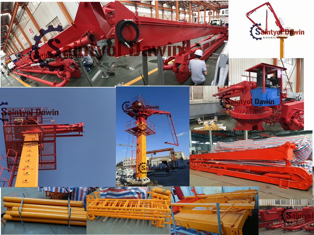
2.1 Boom
The placing boom takes advantage of mature manufacturing platform of boom design of truck-mounted concrete boom from famous manufacturers. On the base of accuracy data, the boom structure is optimized through finite element analysis, modal analysis, dynamics simulation analysis and endurance test on model machine. The accuracy of design and data is assured through powerful test and industrial assess means. The same-class weld manufacturing technique is adopted for the boom, the quality is excellent. The placing range can be changed by assembling or disassembling the extension boom to meet different placing working condition more neatly.
2.2 Rotary table and slewing mechanismÂ
The slewing support is a large-sized bearing which connects the boom and the column, and bears the overturning moment produced by the boom. It is a key component that directly affects the whole machine's safety. The motor redactor is from Comer in Italy. It is in a high speed rate, and long life span and reliable. The hydraulic motor can rotate the slewing table and the boom 365° through the redactor.
----,,.Comer,,,.365°
2.3 Tubular column
The fortified tubular column is adopted. Deformation of the head of the tubular column is 20%~25% less than congener products, it improves the precision for pouring concrete and reduces vibration of the tube.
,20%~25%,.
The connecting structure parts are optimized, and the rigidity of the column is well and the vibration becomes less.
2.4 Climbing device
Two climbing modes are for choice: climbing device on floor and climbing device in elevator well. The climbing structure has been optimized and inclined block auxiliary structure is adopted in the tubular column. All can eliminate the error effectively for drilling holes in the floor.
Â
2.5 Hydraulic system
- The power system adopts electrical engine and plunger pump with high pressure, low flux pulse and low noise.
- Electro-hydraulic stacked directional valves are in good performance and good working condition.
- Balance valves are from Oil Control, they can support safe guard for boom movement.
2.6 Electric control system
2.6.1 The advanced and reliable electricity equipment: DAWIN concrete placing boom has the advanced digital technology control. The electric control box has the flexible outside, excellent manufactory crafts. This equipment runs the high-smart control system reliable, steadily and safely in boom control.
2.6.2 It's all equipped with electric elements from aboard with high reliability. Electric control is comfortable for wired remote control and wireless remote control are all in.
2.7 Vulnerable part
Straight pipe adopts special quench heat treatment which makes the pipe's life is longer than 30000 m3.
,30000.
This series of concrete distributor have reasonable design and reliable structure. The placing structure adopts 360° rotary arm support. The machine is operated by hands and can rotate flexibly. The tower is of a proper height so you can change the placing position freely only by pulling the robe easily. So it is highly efficient, reliable and economic.Â
Â
| Model | Units | HGY29C | ||
| Performance | Max.radius of placing boom | m | 28.9 | |
| Freestanding height (to the joint between the end of the boom and swivel table) () |
m | 22.7 | ||
| Boom articulation | ° | 400 | ||
| Slewing brake | / | always close | ||
| Working temperature | ºC | 0ºC~60ºC | ||
| Total weight | kg | 19100 | ||
| Counter weight | kg | Have no | ||
| Power | / | 380V/50HZ | ||
| Motor | Model | / | Y2-160M-4 | |
| Power | kW | 11 | ||
| Hydraulic system | Pressure | MPa | 30 | |
| Flux | l/min | 18 | ||
| Hydraulic oil | Circumstance temperature 35ºC-50ºC35ºC-50ºC | / | L-HM 68 | |
| Circumstance temperature 5ºC-35ºC5ºC- 35ºC | / | L-HM 46 | ||
| Circumstance temperature -15ºC-5ºC-15ºC-5ºC | / | L-HM 32 | ||
| Control mode | / | Short-haul Control /radio remote control/ | ||
| Pipeline cleaning | / | Wet cleaning/Dry cleaning / |
||
| Structure of tower body | / | Tubular column | ||
| Section of tower body | m×m | 0.75×0.75 | ||
| Boom | Shape | / | Three hydraulic foldable arms R |
|
| Inner diameter of pipeline | mm | DN125 | ||
| End hose | ″×mm | 5″×3000 | ||
| 1st section | Length | m | 11.5 | |
| Articulation | ° | 0°~82.5° | ||
| 2nd section | Length | m | 9.3 | |
| Articulation | ° | 0°~180° Pneumatic Conveying System,Dilute Phase Conveying Systems,Positive Pressure Pneumatic Conveying System,Dense Phase Pneumatic Conveying System Mianyang Liuneng Powder Equipment Co., Ltd , https://www.lnpepowder.com | ||