Protective relays represent a sophisticated aspect of electrical engineering and contracting, often perceived as daunting. However, they don't have to be intimidating! This three-part series aims to introduce basic concepts of relaying to professionals in the solar and energy storage industries who aren't necessarily engineers.
**Part 1: What Are Relays, CTs, & PTs?**
**Part 2: ANSI/IEEE Relay Device Numbers (found below)**
**Part 3: What Does SEL Stand For?**
*Relay Numbers*
Protective relays are designed using standard device numbers to outline their functionality. Instead of relying on verbal descriptions, we use numerical codes to specify the role of a relay. These numbers and acronyms are standardized in the ANSI/IEEE C37.2 document.
*Why Use Numbers Instead of Words?*
1. **Efficiency**: Using numbers significantly streamlines communication. For instance, instead of stating "Over Voltage on the Neutral," one can simply refer to "59N."
2. **Standardization**: When conversing, everyone involved—from utilities to engineers, vendors, and installers—immediately understands the intended functionality without risking miscommunication or errors.
3. **Compactness**: Given that relays perform multiple functions, listing just the numbers makes drawings more concise. Consider a relay with "phase overvoltage & undervoltage, phase over frequency & under frequency, ground inverse time overcurrent, and alarm" functions. Isn’t it much simpler to just use the numbers?
---
*Attention Engineers!*
If you enjoy technical content like this, Pure Power might be the perfect fit for you. Our team of 80 engineers designs over 2,000 commercial and industrial (C&I) and utility-scale solar projects annually. Being surrounded by such expertise can significantly boost your career trajectory.
Explore our job openings [here](#).
---
*Commonly Used Relay Numbers in Solar Systems*
Below are some frequently used functions in photovoltaic (PV) and energy storage systems:
| # | Name | Description |
|---|---------------------|-----------------------------------------------------------------------------------------------|
| 25| Synchronizing Clock | Compares the utility and solar circuit’s voltage, frequency, and phase angle. Allows solar connection if synchronized. |
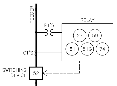
| 27| Undervoltage | Activates when voltage drops below a preset threshold. |
| 32| Directional Power | Triggers when power flow surpasses a specific value in a given direction (Reverse Power Relay). |
| 49| Transformer Thermal| Alerts when winding temperature exceeds a predefined limit. |
| 50| Instantaneous Overcurrent | Triggers when current exceeds a specified value. |
| 51| Inverse-Time Overcurrent | Activates after current exceeds a value for a set duration. |
| 52| Circuit Breaker | A device to open circuits; 52R indicates it can also reclose circuits. |
| 59| Overvoltage | Triggers when voltage surpasses a set point. |
| 74| Alarm | Initiates a visual, audible, or data alert. |
| 79| AC Reclosing | Manages the reclosing or locking out of an AC circuit interrupter. |
| 81| Frequency | Alerts when frequency falls outside acceptable ranges. |
| 86| Lockout | Disables operation until manually reset. |
| 87| Differential Protective | Triggers upon detecting a difference between two measured currents. |
| 89| Line Switch | A device like a disconnect switch; typically used only when electrical accessories are present.|
Additionally, letters appended to the numbers further clarify the function:
| # | Name | Description |
|---|------------|-----------------------------------------------------------------------------------------------|
| R | Reclosing | Adding 'R' means the relay can reclose. Example: 52R is a circuit breaker capable of opening and reclosing circuits. |
| P | Phase | Indicates the function operates on the phases. Often omitted since it's assumed by default, e.g., 50 and 51 overcurrent functions. |
| N | Neutral | Adding 'N' signifies operation on the neutral rather than the phase. Example: 51N monitors neutral for unbalanced overcurrent. |
| G | Ground | Adding 'G' denotes operation on the ground instead of the phase. Example: 51G detects ground faults. |
*Setpoints*
Merely specifying the functions isn't sufficient. Each function requires minimum and/or maximum setpoint values, determined by an engineer and tailored to each project.
*Conclusion*
At first glance, the idea behind relay device numbers seems straightforward. Yet, as you delve deeper, complexity arises rapidly. Fortunately, developers and project managers don't need to grasp these technicalities fully to fulfill their roles. That's where experienced engineers come in, like those at Pure Power. Need assistance with your project's relays? Click [here](#) to learn more or contact us today.
Japanese Car Toyato exhaust manifold assembly,Japanese Car Toyato exhaust manifold adapter,Japanese Car Toyatoexhaust manifold adapter kit
Ningbo Lingmai Machinery Manufacturing Co., Ltd. , https://www.lingmaimfg.com