The electrical schematic of the UV weather resistance test box is shown in Figure 2.1. In the electrical schematic diagram, we can see that the control section of the UV weather resistance test box is mainly implemented in the three parts of the ultraviolet generator, the infrared generator and the fan, and the introduced power supply is a single item of electricity to realize the control of the above three objects. The specific control management is realized by the control unit, and the control command is input through the control panel.
As described earlier, the UV light weather resistance test chamber can realize ozone, ultraviolet ozone, infrared high temperature, ultraviolet ozone, high temperature and other types of products. Through the electrical schematic diagram, we can make a simple explanation: Through the J1, J2, J3 contacts on and off can achieve the corresponding product approach.
Of course, this diagram is only a schematic diagram. It differs from the distribution and numbering of specific electrical components. It only gives a preliminary and brief description. The specific circuit diagram is shown in Figure 2.5. 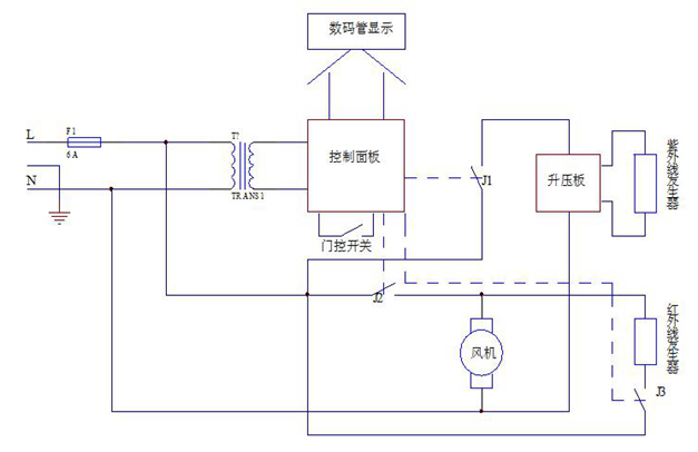
Figure 2.1 Electrical schematic diagram of ultraviolet weather resistance test box
<1> Control Board Principles
1. DC low voltage
As shown in Figure 2.2, the AC voltage coming out of the transformer is filtered by a rectifier bridge composed of four diodes D6, D7, D8, and D9 to obtain a voltage of +12V, and +12V is filtered by a 7805 voltage regulator to obtain +5V. In the figure, the power source of +5v and +12v is specifically marked. 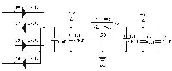
Figure 2.2 Schematic of +12V and +5V
2. Relay control circuit
As shown in Figure 2.3, the 15th, 16th, and 17th pins of the microcontroller control the conduction of the three-level transistors Q1, Q2, and Q3, thereby controlling the pull-in of the intermediate relays KZ2, KZ3, and KZ4 to operate the products, insulation, thaw, and fans. The realization. 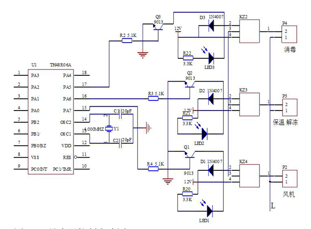
Figure 2.3 relay control circuit
3. Introduction of MCU Chip HT48R06A-1
The HT48R06A-1 is a high-performance 8-bit microcontroller with multiple I/O ports. It has a 2.2-5.5V operating voltage range, 13 I/O lines, a 1024x14-bit program ROM, and 64x8-bit data memory with built-in quartz oscillation. Or RC Oscillator, Watchdog (WDT) Circuit, 2nd Stack, 14-bit Lookup Table Instructions, Instruction Cycle is Only 0.5uS When Clock Frequency Is 8MHz, An 8-Bit Prescaler Timing With 8 Overflow Interrupt Function / Counter, 63 powerful reduced instruction set, 18-pin DIP package.
4. The internal structure of the HT48R06A-1 is shown in Figure 2.4. The main functional characteristics of the HT48R06A-1 are as follows:
A. Working voltage: 2.2-5.5V;
B. suspend and port wake-up function;
C.13 bidirectional I/O input and output lines;
D. Low voltage reset function;
E. An 8-bit programmable timer/counter;
F. Built-in quartz crystal and RC oscillator;
G.63 streamlined instruction set;
H. Watchdog (WDT) circuit;
I.64 × 8 internal data memory RAM;
J. Support PFD buzzer output tone;
K.1024×14 bit program memory ROM;
L. All instructions are 1-2 machine cycles;
M.14 check table instructions;
N.2 level stack;
O. Bit manipulation instructions;
P. Interrupt input is multiplexed with one I/O port.
Specific pin functions are described as follows:
Pins 1-4, 18-15 are PA0-PA7 bidirectional 8-bit input/output ports;
Pins 7-5 are PB0-PB2 bidirectional 3-bit input/output ports;
Pins 9, 10 are bidirectional input/output ports, and they are also external interrupts and timer ports.
Pin 11 is the reset end;
Pin 8 is grounded;
Pins 13, 14 are pulse input and output ports, external crystal or oscillator circuit;
Pin 12 is the power terminal. 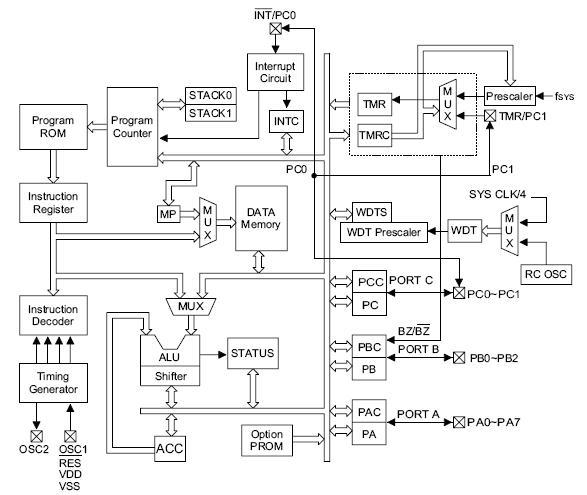
Figure 2.4 HT48R06A internal structure
Laser Engraver,Wood Laser Engraving Machine,Co2 Portable Laser Engraving Machine,Tube Laser Engraving Machine
Jinan Bodor CNC Machine Co., Ltd. , http://www.bodorcnc.com